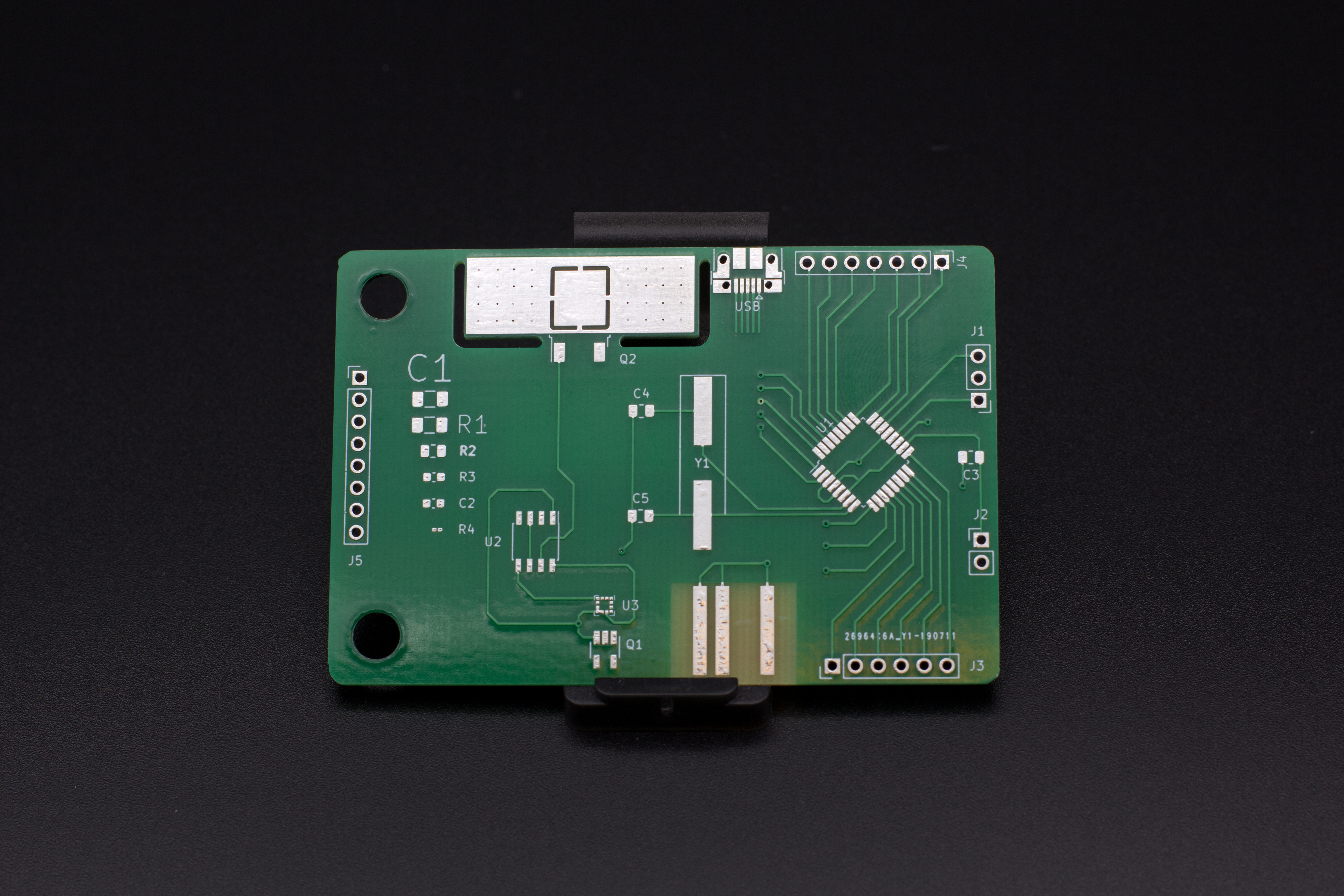


To place these in your design, you need to either make a custom part, or create another PCB design that contains just the holes required for your tab.This is just a bit of bridging PCB, that has an edge perforated with little holes to make it easier to break off.

Hole size and spacing should be on your fab’s recommendations.The width of the part/board should be the width of your routed edge.In my example, I have two rows of holes, even though the boards are linked to a frame.If you’re linking boards directly to other boards, you want two rows of holes, if you are linking boards to a frame, you only need one row of boards, inline with the edge of the board.A custom part is better, but both will work. How JLCPCB showed my boards after importing And what the final product looked likeĪt the same time I had the same boards manufactured with OSH Park. Please, only experience engineer bid on this.They ask for a slightly different layout. You need to give 100% accuracy before production. You need to check all of the footprints, and circuit diagram properly with the power, voltage and current calculation. I want to submit my PCB layout at JLCPCB, you need to make the necessary correction before submit to the manufacturing. That is base on ESP-Wrover module, GSM module, I2C Pressure sensor, USB to UART module, and power over ethernet module. I want to review each block of my circuit. While aesthetics of the design and component footprint accuracy should also be taken into account, they should be secondary considerations. The primary focus should be on checking the correctness of the electrical circuit. The files should be checked at the design completion stage, and then submitted to the manufacturer after that. I am looking for an experienced engineer to review the schematic and PCB layout files before production.


 0 kommentar(er)
